Civil Rights
Movements, leaders, victories and the continuing fight for equality.

Explore the people, places, events, achievements, struggles and stories that shaped our journey.
Movements, leaders, victories and the continuing fight for equality.
Innovation, patents, science, technology and world-changing contributions.
Pioneers, champions, Negro Leagues, records, activism and excellence.
Meet the people whose lives, choices and achievements shaped the journey.
Black towns, communities, institutions and places where history happened.
Moments that changed communities, movements, institutions and the nation.
In 1968 Shirley Chisholm became the first Black woman elected to the United States Congress. In 1972 she launched a campaign for the Democratic presidential nomination, breaking another political barrier.
MORE →Reflects the personal views, recollections, and perspective of the author, Mike Davis.
This is a personal recollection on the Move fire on May 13, 1985


In electronics, a decoupling capacitor is a capacitor used to decouple (i.e. prevent electrical energy from transferring to) one part of a circuit from another. Noise caused by other circuit elements is shunted through the capacitor, reducing its effect on the rest of the circuit. For higher frequencies, an alternative name is bypass capacitor as it is used to bypass the power supply or other high-impedance component of a circuit.
Active devices of an electronic system (e.g. transistors, integrated circuits, vacuum tubes) are connected to their power supplies through conductors with finite resistance and inductance. If the current drawn by an active device changes, the voltage drop from the power supply to the device will also change due to these impedances. If several active devices share a common path to the power supply, changes in the current drawn by one element may produce voltage changes large enough to affect the operation of others – voltage spikes or ground bounce, for example – so the change of state of one device is coupled to others through the common impedance to the power supply. A decoupling capacitor provides a bypass path for transient currents, instead of flowing through the common impedance.[1]
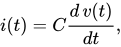
The decoupling capacitor works as the device’s local energy storage. The capacitor is placed between the power line and the ground to the circuit the current is to be provided. According to the capacitor current–voltage relation
a voltage drop between a power line and the ground results in a current drawn out from the capacitor to the circuit. When capacitance C is large enough, sufficient current is supplied to maintain an acceptable range of voltage drop. The capacitor stores a small amount of energy that can compensate for the voltage drop in the power supply conductors to the capacitor. To reduce undesired parasitic equivalent series inductance, small and large capacitors are often placed in parallel, adjacent to individual integrated circuits (see § Placement).
In digital circuits, decoupling capacitors also help prevent radiation of electromagnetic interference from relatively long circuit traces due to rapidly changing power supply currents.
Decoupling capacitors alone may not suffice in such cases as a high-power amplifier stage with a low-level pre-amplifier coupled to it. Care must be taken in the layout of circuit conductors so that heavy current at one stage does not produce power supply voltage drops that affect other stages. This may require re-routing printed circuit board traces to segregate circuits, or the use of a ground plane to improve the stability of power supply.


A bypass capacitor is often used to decouple a subcircuit from AC signals or voltage spikes on a power supply or other line. A bypass capacitor can shunt energy from those signals, or transients, past the subcircuit to be decoupled, right to the return path. For a power supply line, a bypass capacitor from the supply voltage line to the power supply return (neutral) would be used.
High frequencies and transient currents can flow through a capacitor to circuit ground instead of to the harder path of the decoupled circuit, but DC cannot go through the capacitor and continues to the decoupled circuit.
Another kind of decoupling is stopping a portion of a circuit from being affected by switching that occurs in another portion of the circuit. Switching in subcircuit A may cause fluctuations in the power supply or other electrical lines, but you do not want subcircuit B, which has nothing to do with that switching, to be affected. A decoupling capacitor can decouple subcircuits A and B so that B doesn't see any effects of the switching.
In a subcircuit, switching will change the load current drawn from the source. Typical power supply lines show inherent inductance, which results in a slower response to changes in current. The supply voltage will drop across these parasitic inductances for as long as the switching event occurs. This transient voltage drop would be seen by other loads as well if the inductance between two loads is much lower compared to the inductance between the loads and the output of the power supply.
To decouple other subcircuits from the effect of the sudden current demand, a decoupling capacitor can be placed in parallel with the subcircuit, across its supply voltage lines. When switching occurs in the subcircuit, the capacitor supplies the transient current. Ideally, by the time the capacitor runs out of charge, the switching event has finished, so that the load can draw full current at normal voltage from the power supply and the capacitor can recharge. The best way to reduce switching noise is to design a PCB as a giant capacitor by sandwiching the power and ground planes across a dielectric material.[citation needed]
Sometimes parallel combinations of capacitors are used to improve response. This is because real capacitors have parasitic inductance, which causes the impedance to deviate from that of an ideal capacitor at higher frequencies.[2]
Transient load decoupling as described above is needed when there is a large load that gets switched quickly. The parasitic inductance in every (decoupling) capacitor may limit the suitable capacity and influence the appropriate type if switching occurs very fast.
Logic circuits tend to do sudden switching (an ideal logic circuit would switch from low voltage to high voltage instantaneously, with no middle voltage ever observable). So logic circuit boards often have a decoupling capacitor close to each logic IC connected from each power supply connection to a nearby ground. These capacitors decouple every IC from every other IC in terms of supply voltage dips.
These capacitors are often placed at each power source as well as at each analog component in order to ensure that the supplies are as steady as possible. Otherwise, an analog component with a poor power supply rejection ratio (PSRR) will copy fluctuations in the power supply onto its output.
In these applications, the decoupling capacitors are often called bypass capacitors to indicate that they provide an alternate path for high-frequency signals that would otherwise cause the normally steady supply voltage to change. Those components that require quick injections of current can bypass the power supply by receiving the current from the nearby capacitor. Hence, the slower power supply connection is used to charge these capacitors, and the capacitors actually provide large quantities of high-availability current.
A transient load decoupling capacitor is placed as close as possible to the device causing the transient. This minimizes the amount of line inductance and series resistance between the decoupling capacitor and the device. The longer the conductor between the capacitor and the device, the more inductance is present.
Since capacitors differ in their high-frequency characteristics, decoupling commonly involves the use of a combination of capacitors. For example in logic circuits, a common arrangement is ~100 nF ceramic per logic IC (multiple ones for complex ICs), combined with electrolytic or tantalum capacitor(s).
These photos show old printed circuit boards with through-hole capacitors, where as modern boards typically have tiny surface-mount capacitors.


Source: Wikipedia. Article content is retrieved live through the MediaWiki API.

In electronics, a decoupling capacitor is a capacitor used to decouple (i.e. prevent electrical energy from transferring to) one part of a circuit from another. Noise caused by other circuit elements is shunted through the capacitor, reducing its effect on the rest of the circuit. For higher frequencies, an alternative name is bypass capacitor as it is used to bypass the power supply or other high-impedance component of a circuit.

A polymer capacitor, or more accurately a polymer electrolytic capacitor, is an electrolytic capacitor (e-cap) with a solid conductive polymer electrolyte. There are four different types: Polymer tantalum electrolytic capacitor (Polymer Ta-e-cap) Polymer aluminium electrolytic capacitor (Polymer Al-e-cap) Hybrid polymer capacitor (Hybrid polymer Al-e-cap) Polymer niobium electrolytic capacitors Polymer Ta-e-caps are available in rectangular surface-mounted device (SMD) chip style. Polymer Al-e-caps and hybrid polymer Al-e-caps are available in rectangular surface-mounted device (SMD) chip style, in cylindrical SMDs (V-chips) style or as radial leaded versions (single-ended). Polymer electrolytic capacitors are characterized by particularly low internal equivalent series resistances (ESR) and high ripple current ratings. Their electrical parameters have similar temperature dependence, reliability and service life compared to solid tantalum capacitors, but have a much better temperature dependence and a considerably longer service life than aluminium electrolytic capacitors with non-solid electrolytes. In general polymer e-caps have a higher leakage current rating than the other solid or non-solid electrolytic capacitors. Polymer electrolytic capacitors are also available in a hybrid construction. The hybrid polymer aluminium electrolytic capacitors combine a solid polymer electrolyte with a liquid electrolyte. These types are characterized by low ESR values but have low leakage currents and are insensitive to transients, however they have a temperature-dependent service life similar to non-solid e-caps. Polymer electrolytic capacitors are mainly used in power supplies of integrated electronic circuits as buffer, bypass and decoupling capacitors, especially in devices with flat or compact design. Thus they compete with MLCC capacitors, but offer higher capacitance values than MLCC, and they display no microphonic effect (such as class 2 and 3 ceramic capacitors).

An electrolytic capacitor is a polarized capacitor whose anode or positive plate is made of a metal that forms an insulating oxide layer through anodization. This oxide layer acts as the dielectric of the capacitor. A solid, liquid, or gel electrolyte covers the surface of this oxide layer, serving as the cathode or negative plate of the capacitor. Because of their very thin dielectric oxide layer and enlarged anode surface, electrolytic capacitors have a much higher capacitance-voltage (CV) product per unit volume than ceramic capacitors or film capacitors, and so can have large capacitance values. There are three families of electrolytic capacitor: aluminium electrolytic capacitors, tantalum electrolytic capacitors, and niobium electrolytic capacitors. The large capacitance of electrolytic capacitors makes them particularly suitable for passing or bypassing low-frequency signals, and for storing large amounts of energy. They are widely used for decoupling or noise filtering in power supplies and DC link circuits for variable-frequency drives, for coupling signals between amplifier stages, and storing energy as in a flashlamp. Electrolytic capacitors are polarized components because of their asymmetrical construction and must be operated with a higher potential (i.e., more positive) on the anode than on the cathode at all times. For this reason the polarity is marked on the device housing. Applying a reverse polarity voltage, or a voltage exceeding the maximum rated working voltage of as little as 1 or 1.5 volts, can damage the dielectric causing catastrophic failure of the capacitor itself. Failure of electrolytic capacitors can result in an explosion or fire, potentially causing damage to other components as well as injuries. Bipolar electrolytic capacitors which may be operated with either polarity are also made, using special constructions with two anodes connected in series. A bipolar electrolytic capacitor can be made by connecting two normal electrolytic capacitors in series, anode to anode or cathode to cathode, along with diodes.
Block capacitor may refer to: DC-blocking capacitor also known as coupling capacitor a misnomer for a decoupling, reservoir or smoothing capacitor, possibly due to the German term Blockkondensator
Before the 1921 destruction of Tulsa’s Greenwood District, Black residents had created a remarkable center of business and community life. The district included stores, professional offices, entertainment venues and homes owned by Black citizens. Understanding Greenwood means learning what was built—not only what was burned.
MORE →Brown v. Board of Education in 1954.